Follow the quick start guide. It is included with your order and can also be found under each product and at the bottom of this page. Double-check that all values in menus 10–14 are correct. Also, watch the installation video under each product. It is also available at the bottom of this page.
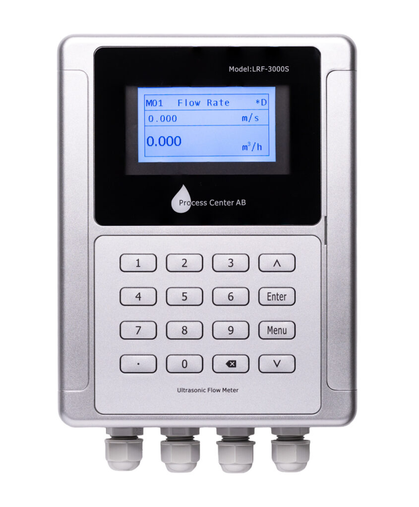
Check the letter in the upper right corner of the display.
"R " indicates that the meter is set correctly in menus 10–14
"E" means there is no signal between the sensors. Verify the settings in menu 10-14
"D" indicates a weak signal between the sensors and that the meter is attempting to adjust the gain between the sensors. Move one of the sensors slightly
Start by checking the values you entered in menus 10–14 to make sure they are correct (plastic = PVC). Double-check the information in the quick start guide.
Sand the pipes to remove paint, rust, or buildup. Fill with grease until it overflows. Do not tighten too much, or the grease will be forced out.
The sensors should be mounted in the middle of the pipe at the 9 and 3 o'clock positions, aligned with each other.
Set the correct distance between the sensors according to Menu 14—try adjusting one sensor a few millimeters at a time. The distance is measured from inner edge to inner edge in millimeters.
The label should face outward, and the cables should run outward from each other, right to left.
Start with the V method up to the DN200 replacement, and switch to the Z method if that doesn't work.
Are there bends, valves, pumps, etc., near the sensors?
The recommended distance is 10 times the pipe diameter in front of the first sensor and 5 times the pipe diameter
If the above does not work, it is most likely air or turbulence. Turn off the flow and perform a zero-flow calibration in Menu 22. Then try again with the flow still turned off. If the Q value is correct, there is air in the system and it needs to be vented.
Move one of the sensors a few millimeters at a time along the pipe until its ratio reads between 97% and 103%
Go to Menu 04. The signal strength should be above 80 (UP, DN) and Q should be between 60 and 100. Go to “Sound,” where the value should be between 97 and 103%. If these values are correct and “R” is displayed in the upper right corner, the meter is installed correctly.
Menu 04 shows the correct Q value (between 60 and 100) and Ratio (should be between 97 and 103%), but no flow is shown in Menu 01. The flow is likely less than 0.03%. Adjust the value downward in Menu 21 (low flow cut-off). If there is still no flow, the pipe is too large. If possible, reduce the pipe size; this will increase the flow.
Using the Z-method. The Sound value is 80 but the Q-value is 0, even when the sensors are moved. There is too little fluid in the pipe, which makes it impossible to measure using ultrasound. The fluid must cover the sensors. This is a common problem with sprinkler systems.
If the tubes are not completely full, the measurement will be incorrect. Go to Menu 26 and change the scaling factor. It is set to 1. If the tubes are ¾ full, change it to 0.75.
The Modbus protocols are listed at the end of the manual. Modbus settings in the M30:
The default communication settings are 9600 baud (can be changed), no parity (None, cannot be changed), 8 data bits, 1 stop bit, and 1 start bit. The default Modbus address is 55 (can be changed):
See the information on registers at the end of the manual
M-bus is an optional feature that must be selected when placing an order
Settings are configured in Menu32
Test the analog output in Menu32 under the "Check" tab
If the liquid in question is not listed in the preset menu (Menu 12), you can find it in the document “Acoustic Properties of Liquids.” Similarly, to change the temperature, refer to “Acoustic Properties of Liquids.” Select “Other” and make the changes according to this document. The document can be found on each product page, under the “Documents” tab.
The flow meter is calibrated for water at 20 degrees. For water at approximately 80 degrees or higher, the meter should be adjusted according to the document.
Perform this in Menu 22. Make sure the tube is filled with liquid and that the liquid is at rest in the tube. Zero-flow calibration takes about 30 seconds. If it doesn't work the first time, try it again.
Check that the correct parameters are used in Menu 10-14
Check Menu 04, the "Sound" tab, to ensure that the "Ratio" value is between 97-103%
Check that zero-flow calibration has been performed
Is the flow meter's sound velocity set to the correct fluid and temperature?
Note: All flow meters have some degree of inaccuracy. It is therefore very difficult to get two meters to show exactly the same flow or energy reading
If the checks above are correct, the meter is installed properly. Proceed then to check the permanently installed meters. Permanently installed meters may need to be calibrated after a few years
The supply and return lines have been swapped during installation
Swap the positions of the sensors or swap the cable connections in the meter