Follow the quick start guide. It is included with your order and can also be found under each product and at the bottom of this page. Double-check that all values in menus 10–14 are correct. Also, watch the installation video under each product. It is also available at the bottom of this page.
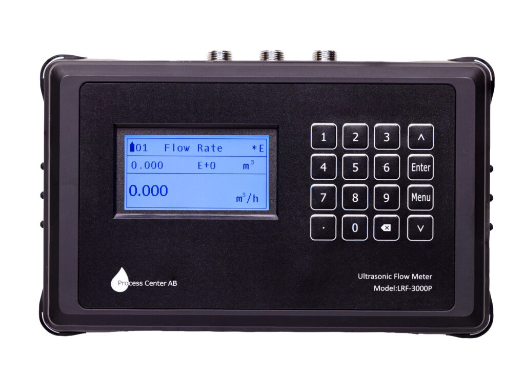
Check the letter in the upper right corner of the display.
"R " indicates that the meter is set correctly in menus 10–14
"E" means there is no signal between the sensors. Verify the settings in menu 10-14
"D" indicates a weak signal between the sensors and that the meter is attempting to adjust the gain between the sensors. Move one of the sensors slightly
Start by checking the values you entered in menus 10–14 to make sure they are correct (plastic = PVC). Double-check the information in the quick start guide.
Sand the pipes if there is paint, rust, or a coating. Fill with contact grease until it overflows. Do not tighten too much, or the grease will be squeezed out.
The sensors must be mounted in the middle of the pipe at the 9 o'clock or 3 o'clock positions, aligned with each other.
For measurement method Z, the sensors must be mounted at the 3 o'clock and 9 o'clock positions.
Set the correct distance between the sensors according to menu 14—try adjusting one sensor a few millimeters at a time. The distance is measured from inner edge to inner edge in millimeters.
The label should face outward, and the cables should run outward from each other, right to left.
Börja med V metoden upp till DN200-byt och till Z metoden om ej fungerar. Mätmetod Z kan vara lämplig att användas på rör < DN32. Finns det böjar/ventiler/pumpar, etc i närheten av givarna?. Rekommenderat avstånd är 10xrördiameterna framför första givaren och 5Xrördiametern efter nedströmsgivaren. Äldre pumpar kan skapa turbulent vatten, öka då avståndet till 30x uppströms och 10x nedströms. Om inget fungerar trol luft/turbulens. Stäng av flödet och gör nollflödeskalibrering. Prova därefter igen. Om Q värdet är är bra är det luft i systemet och behöver luftas.
Move one of the sensors a few millimeters at a time along the pipe until its ratio reads between 97% and 103%
Go to Menu 04. The signal strength should be above 80 (UP, DN) and Q should be between 60 and 100. Go to “Sound,” where the value should be between 97 and 103%. If these values are correct, the meter is installed properly.
Menu 04 shows the correct Q value (between 60 and 100) and Ratio (should be between 97 and 103%), but no flow is shown in Menu 01. The flow is likely less than 0.03%. Adjust the value down in Menu 21 (cut-off) and see if that works. If it shows a flow rate, then the pipe is too large for the flow. The pipe diameter needs to be reduced to increase the flow rate.
The Z-method. Shows a value of 80 in S but 0 in Q, even when the sensors are moved. There is too little fluid in the pipe, so ultrasonic measurement is not possible. The fluid must cover the sensors. This is a common problem with sprinkler systems.
If the tubes are not completely filled, the measurement will be incorrect. Go to menu 26 and change the scaling factor. It is set to 1. If the tubes are ¾ full, change it to 0.75.
The Modbus protocols are listed at the end of the manual. Modbus settings in the M30:
The default communication settings are 9600 baud (can be changed), no parity (None, cannot be changed), 8 data bits, 1 stop bit, and 1 start bit. The default Modbus address is 55 (can be changed):
See the information on registers at the end of the manual.
M-Bus is an option; please specify this when ordering
Different liquids and temperatures have different acoustic properties. Refer to our documents for the acoustic properties of various liquids. Enter the speed of sound for the selected liquid in Menu 12.
The flow meter is calibrated for water at 20 degrees.
Check that the correct parameters are used in menus 10–14
Check Menu 04, the “Sound” tab, to ensure that the “Ratio” value is between 97–103%
Check that zero-flow calibration has been performed
Is the flow meter’s sound velocity set to the correct fluid and temperature?
Note: All flow meters have some degree of inaccuracy, so it is difficult to get two meters to display exactly the same flow rate or energy consumption
If the checks above are correct, the meter is installed properly. Proceed to check the permanently installed meters. Permanently installed meters may need to be calibrated after a few years
Settings in Menu 32
Testing the analog output in Menu 32 under the "Check" tab
Perform this in Menu 22. Make sure the tube is filled with liquid and that the liquid is at rest in the tube. Zero-flow calibration takes about 30 seconds to complete.
If it doesn't work the first time, try again